

Window energy modeling is the process of calculating a window system’s thermal and optical behaviour and expressing it as performance indices — U-factor, SHGC, visible transmittance, and annual energy indices — that feed directly into whole-building energy simulations and HVAC sizing decisions. The governing standards are ISO 15099 and NFRC test procedures; the primary toolchain runs through Berkeley Lab’s WINDOW and THERM software into EnergyPlus for whole-building calculations.
Three practical points every practitioner should keep in mind from the start:
- Detailed vs simplified methods: Use the layer-by-layer approach with TARCOG/WinCalc and THERM frame modelling when façade performance materially affects HVAC sizing or when certification is required. Use EnergyPlus’s
WindowMaterial:SimpleGlazingSystemfor rapid screening studies where only U-factor and SHGC are available. - Essential indices for BEM: U-factor and SHGC are the minimum inputs for any whole-building model; VT is required when daylighting is modelled; annual EPc/EPh indices are needed for ENERGY STAR Canada certification workflows.
- Validation must-haves: Every model must be checked against NFRC-certified lab values or IGDB/CGDB spectral data before results are used for compliance or procurement. Undocumented assumptions about frame conductivity and edge-of-glass geometry are the most common source of error.
Table of Contents
- How does window energy modeling fit into building energy assessment?
- What physics and algorithms drive window thermal calculations?
- What performance metrics do window models return?
- What inputs and data sources does accurate window modeling require?
- Which software tools should you use, and how do they connect?
- Detailed vs simplified modeling: how do you choose?
- Why do frame and edge-of-glass effects matter so much?
- How do window model outputs feed HVAC sizing and whole-building models?
- How do you validate and quantify uncertainty in window models?
- What standards and certifications govern Canadian window modeling practice?
- A practical step-by-step workflow for Canadian modelers
- Key takeaways
- A practitioner’s perspective on where window modeling adds the most value
- Authoritative references for technical reports
How does window energy modeling fit into building energy assessment?
Window energy modeling sits at the intersection of component-level physics and whole-building simulation. The chain runs in three stages: component-level inputs (spectral optical properties, gas fills, frame geometry) feed into whole-window aggregation tools like WINDOW and THERM, which produce certified indices that a whole-building engine like EnergyPlus consumes for hourly load calculations. Building energy modeling integrates geometry, construction materials, lighting, HVAC, and occupancy schedules against local weather data, with calculations running hourly or more frequently over a full year.
Windows are rarely modelled in isolation. Mechanical engineers rely on BEM as the foundation for HVAC system sizing, and window thermal performance often drives peak load calculations more than any other envelope component. A poorly specified glazing system can inflate cooling loads in Toronto’s humid summers or increase heating demand through a long Ontario winter, both of which cascade directly into equipment selection and operating costs.
Who uses window energy modeling:
- Energy consultants preparing compliance submissions under the National Building Code of Canada or provincial energy codes
- LCA/LCC analysts assessing lifecycle energy and cost performance of window systems
Typical use cases in Canadian practice:
- Lifecycle assessment and costing inputs for window system procurement decisions
What physics and algorithms drive window thermal calculations?
Two coupled physics problems govern every window energy model: spectral optical transfer through the glazing layers and thermo-fluid heat transfer across the full assembly. Solving them together is what makes window modeling computationally non-trivial.
The optical problem involves tracking solar and visible radiation through each glazing layer using spectral transmittance and reflectance data, integrating across the solar spectrum to produce broadband indices. The thermal problem involves solving an energy balance across each gas gap and solid layer, coupling conduction through glass, convective exchange in gas gaps, and long-wave radiative exchange between surfaces. For a system with n glazing layers, the algorithm must solve a system of 4n equations iteratively until temperatures converge.
Layer-by-layer spectral approach vs equivalent-layer simplification
The layer-by-layer approach, implemented in WINDOW through its TARCOG and WinCalc calculation engines, treats each glazing layer as a distinct optical and thermal element. WINDOW’s technical documentation describes how the software implements ISO 15099 algorithms, performing spectral and broadband integrations to output centre-of-glass and whole-window metrics including Ug, Tsolg, VTg, SHGC, and condensation resistance. WinCalc is the newer portable calculation engine; practitioners should confirm which engine their version of EnergyPlus invokes to maintain reproducibility across project files.
The equivalent-layer simplification, used in EnergyPlus’s WindowMaterial:SimpleGlazingSystem, converts a known U-factor and SHGC pair into a single equivalent glazing layer for whole-building simulation. This approach is faster and requires fewer inputs, but it sacrifices angular dependence and spectral resolution.
Key algorithmic steps in the detailed approach:
- Retrieve spectral optical data (transmittance, front and back reflectance at each wavelength) from IGDB or CGDB for each glazing layer
- Integrate spectrally to produce solar-weighted and photopic-weighted broadband properties
- Apply the TARCOG iterative solver to compute gas-gap temperatures, convective coefficients, and radiative exchange between surfaces
- Converge on a consistent temperature distribution across all layers
- Aggregate centre-of-glass results with frame and edge-of-glass contributions using area weighting
Matrix-based methods, such as the Klems bidirectional scattering distribution function (BSDF) matrices, are required when shading devices or complex coatings are present. Simple shading coefficients are often insufficient for accurate year-round solar gain predictions in these cases. Peer-reviewed comparisons from IBPSA document the accuracy trade-offs between spectral/detailed models and simplified approaches, confirming that method choice has a measurable impact on annual energy predictions.
What performance metrics do window models return?
Window energy models return a defined set of indices that map directly to building performance decisions. Understanding what each metric measures and what range is appropriate for Canadian conditions is a prerequisite for using model outputs correctly.
| Metric | What it measures | Typical range | Canadian climate note |
|---|---|---|---|
| U-factor (W/m²·K) | Rate of non-solar heat transfer through the assembly | 0.8 W/m²·K | Lower is better; cold climates (Zone 6–8) require low U-factor values for ENERGY STAR |
| SHGC (dimensionless) | Fraction of incident solar radiation admitted as heat | — | Higher SHGC beneficial for heating-dominated zones; lower for cooling-dominated |
| Visible transmittance (VT) | Fraction of visible light transmitted | — | Higher VT reduces artificial lighting loads; trade-off with SHGC in low-e coatings |
| Condensation resistance (CR) | Resistance to interior surface condensation (NFRC scale 0–100) | — | Higher CR critical for humid interior environments in Canadian winters |
| EPc / EPh (kWh/m²·yr) | Annual cooling / heating energy penalty or benefit | Project-specific | Used in AERC and ENERGY STAR Canada certification workflows |
ENERGY STAR guidance defines climate-based U-factor and SHGC thresholds mapped to NFRC test procedures. For Canadian projects, the relevant climate zones span from Zone 4 (southern British Columbia) through Zone 8 (northern territories), and the desirable metric ranges shift substantially across that span.
How these metrics feed BEM decisions:
- SHGC — controls the solar heat gain schedule in EnergyPlus; in heating-dominated Canadian climates, south-facing glazing with higher SHGC can offset heating loads, but the same specification on east or west exposures increases summer cooling demand.
For window placement decisions in Canadian homes, orientation-specific SHGC selection is one of the highest-leverage choices a designer can make before construction begins.
What inputs and data sources does accurate window modeling require?
Accurate window energy modeling depends entirely on the quality of its inputs. A well-structured model with poor spectral data will produce plausible-looking but unreliable results. Collecting the right data before opening any simulation tool saves significant rework.
Required inputs by category:
- About building energy modeling | Department of Energy
- WINDOW technical documentation (Berkeley Lab)
- AERC WINDOW/THERM simulation manual (LBNL)
- Window calculation module: engineering reference — EnergyPlus
- Window software downloads | Windows & Daylighting (LBNL)
- Guide to energy-efficient windows | ENERGY STAR (EPA)
- A comparison of the latest window modeling methods (IBPSA conference paper)
- Energy simulation and modeling for window system (ScienceDirect article)
- Modeling windows in DOE 2.1E (LBNL / ETA)
Trusted data sources:
- LBNL WINDOW software libraries: — bundled spectral datasets for common glazing types
QA checks before modelling:
Pro Tip: Always record the IGDB product ID, version number, and download date in your project file. Spectral data is periodically updated in the database, and a version mismatch between your model and a future audit can invalidate compliance documentation.
Which software tools should you use, and how do they connect?
The LBNL toolchain covers the full modelling chain from glazing optics through frame heat transfer to whole-building simulation. Each tool has a defined scope, and understanding where one hands off to the next prevents both gaps and duplication.
The WINDOW software suite includes THERM, RESFEN, and supporting utilities. WINDOW handles glazing spectral calculations and centre-of-glass thermal performance, implementing ISO 15099 through its TARCOG and WinCalc engines. THERM performs 2-D finite-element heat transfer for frames and edge-of-glass regions. Together, they produce whole-window U-factor, SHGC, VT, and angular properties that whole-building tools consume.
| Tool | Primary function | Key outputs | Interoperability |
|---|---|---|---|
| WINDOW (LBNL) | Glazing spectral and centre-of-glass thermal calculations | U-factor, SHGC, VT, CR, angular properties | Exports to THERM; generates window library files for EnergyPlus |
| THERM (LBNL) | 2-D frame and edge-of-glass heat transfer | Frame U-factor, edge-of-glass U-factor, isotherms | Imports from WINDOW; results feed whole-window aggregation in WINDOW |
| WinCalc / TARCOG | Portable calculation engines for glazing thermal performance | Centre-of-glass temperatures, U-factor, SHGC | Integrated into WINDOW and EnergyPlus; TARCOG is the ISO 15099 solver |
| EnergyPlus | Whole-building energy simulation | Annual and peak loads, zone temperatures, HVAC sizing inputs | Accepts WINDOW library files (detailed) or SimpleGlazingSystem inputs (simplified) |
| RESFEN | Residential fenestration annual energy use | Annual heating and cooling energy for residential window selection | Standalone; uses WINDOW outputs |
| AERCalc | Annual energy rating calculation | EPc, EPh annual indices for AERC certification | Uses WINDOW/THERM outputs per the AERC simulation manual |
Interoperability workflow:
- WINDOW exports a
.w7or equivalent window library file containing the full spectral and thermal description of the glazing system - EnergyPlus reads this file directly in its detailed layer-by-layer mode, invoking WinCalc/TARCOG internally for each timestep
- For the simplified path, only U-factor and SHGC are passed to EnergyPlus via
WindowMaterial:SimpleGlazingSystem; the engine then constructs an equivalent single layer - THERM results (frame and edge U-factors) are entered into WINDOW to complete the whole-window aggregation before export
The LBNL Windows-CalcEngine is also available as an open-source API on GitHub, enabling integration of WINDOW/TARCOG calculations into custom simulation environments or automated certification workflows. This is particularly useful for researchers building parametric glazing studies or automated compliance tools.
For practitioners working on window heat loss reduction, understanding which tool produces which output prevents the common mistake of using centre-of-glass U-values as whole-window values in BEM.
Detailed vs simplified modeling: how do you choose?
The choice between detailed layer-by-layer modeling and the simplified equivalent-layer approach comes down to four factors: project goals, accuracy requirements, available inputs, and computational budget.
Decision checklist:
- Does the project require NFRC-certified or ENERGY STAR Canada outputs? Use the detailed approach.
- Is the window façade a dominant load driver (large glazed area, high-performance specification)? Use the detailed approach.
- Are spectral optical data available from IGDB or manufacturer test reports? Detailed approach is feasible.
- Is this a rapid screening study with only U-factor and SHGC known? Use
WindowMaterial:SimpleGlazingSystem. - Are shading devices or complex coatings present? Detailed approach with BSDF matrices is required.
Step-by-step: detailed workflow
- Retrieve spectral data for each glazing layer from IGDB; confirm product IDs and versions.
- Build the glazing system in WINDOW: define layers, gas fills, gap widths, and coating positions.
- Run WINDOW’s TARCOG solver to obtain centre-of-glass U-factor, SHGC, and VT.
- Export the frame cross-section geometry to THERM; assign material properties and boundary conditions per ISO 15099 or NFRC 100.
- Run THERM to obtain frame and edge-of-glass U-factors.
- Return THERM results to WINDOW for area-weighted whole-window aggregation.
- Export the completed window library file to EnergyPlus.
- Assign the window to the appropriate surface in the EnergyPlus model and confirm orientation and shading schedules.
Step-by-step: simplified workflow
- Obtain certified U-factor and SHGC from NFRC documentation or manufacturer data sheets.
- Define a
WindowMaterial:SimpleGlazingSystemobject in EnergyPlus with those two values. - EnergyPlus constructs an equivalent single layer internally; the engineering reference documents the conversion algorithm.
- Run the simulation and note that angular dependence and spectral resolution are approximated.
- Document the simplification assumption explicitly in the model report.
Accuracy trade-offs: The simplified method introduces errors in annual solar gain predictions when angular optical behaviour deviates significantly from the default assumptions, particularly for tilted glazing or high-performance low-e coatings. IBPSA comparative studies confirm that method choice affects annual energy predictions, with the simplified approach performing adequately for standard vertical glazing in screening studies but diverging for complex systems. Document which approach was used, the version of EnergyPlus, and the source of input data in every model report.
Why do frame and edge-of-glass effects matter so much?
Centre-of-glass performance is modelled with 1-D thermal analysis, but frames and edge-of-glass regions require 2-D finite-element methods because heat flows laterally through the frame and spacer as well as perpendicular to the surface. Area-weighted aggregation then combines these three contributions into the whole-window U-factor. Treating centre-of-glass performance as representative of the whole window is one of the most common and consequential errors in building energy assessment.
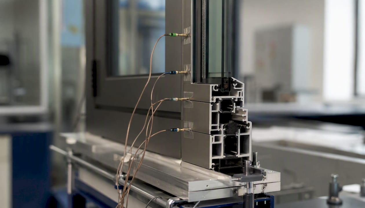
A practical illustration: a triple-pane glazing unit with a centre-of-glass U-factor of 0.8 W/m²·K can easily yield a whole-window U-factor of 1.2–1.6 W/m²·K once an aluminium frame and a standard aluminium spacer are included. Switching to a fibreglass or PVC frame with a warm-edge spacer can bring the whole-window value back below 1.0 W/m²·K. The role of frame material in whole-window performance is therefore not a secondary consideration.
THERM modelling notes:
- Use boundary conditions from ISO 15099 or NFRC 100 consistently; mixing boundary condition sets invalidates comparisons
- Apply a sufficiently fine mesh at material interfaces, particularly at the spacer-to-glass junction where temperature gradients are steepest
- Use THERM’s built-in templates for common frame types as a starting point, but verify that material properties match the actual product specification
- Model the full cross-section including glazing pocket geometry; simplified rectangular approximations underestimate frame conductance for complex extruded profiles
Common pitfalls and their signatures in results:
- Missing or incorrect spacer conductivity: whole-window U-factor is lower than expected; edge-of-glass isotherm shows unrealistically uniform temperature
- Edge seal degradation not modelled: model predicts no condensation risk at the edge; field thermography shows cold spots at the perimeter
- Inappropriate boundary conditions: results do not match NFRC certified values for the same product; check whether indoor and outdoor film coefficients match the standard
- 2-D effects ignored for sloped glazing: centre-of-glass calculation underestimates convective coupling in tilted gas gaps; use THERM’s tilt-angle settings
When field thermography or infrared surface temperature measurements are available, they provide a direct check on THERM predictions at the frame and edge. Discrepancies of more than a few degrees Celsius at the interior surface warrant a review of spacer and frame material inputs.
How do window model outputs feed HVAC sizing and whole-building models?
Window indices enter EnergyPlus at the surface level and propagate through the load calculation chain to HVAC sizing. The mapping is direct: U-factor controls the conductive heat transfer coefficient for each window surface; SHGC controls the solar heat gain multiplier applied to the incident irradiance schedule; VT feeds the daylighting model’s illuminance calculations.
Metric-to-load mapping in EnergyPlus:
- U-factor contributes to the zone’s conductive heat loss/gain term in every timestep; it appears in the surface heat balance alongside the outdoor film coefficient and the indoor convective coefficient
- SHGC is applied to the direct and diffuse solar irradiance on each window surface; EnergyPlus uses angular-dependent SHGC curves when the detailed window library is loaded, or a fixed value when the simplified method is used
- VT feeds the split-flux daylighting model; a higher VT reduces the lighting power density schedule, which in turn reduces internal gains and cooling load
- Frame U-factor contributes separately through the frame area fraction; this is why whole-window values must be used, not centre-of-glass values alone
Recommended sensitivity tests before finalising HVAC sizing:
- Vary U-factor by ±0.2 W/m²·K across the full glazing area and observe the change in peak heating load; for large commercial façades this range often shifts peak load by 5–15%
- Vary SHGC by ±0.05 on south-facing glazing and observe the change in peak cooling load and annual heating energy; the direction of impact reverses between heating and cooling seasons
- Test the frame U-factor contribution by substituting a high-conductance aluminium frame for the specified warm-edge frame; the difference in whole-window U-factor directly quantifies the value of the frame upgrade
Documenting these sensitivity results in the HVAC calculation report is good practice and is increasingly expected by code reviewers and energy auditors. State the window specification, the source of the indices (NFRC certified, WINDOW simulation, or simplified), and the sensitivity range tested. For energy-efficient windows in Ontario, the combination of low U-factor and orientation-optimised SHGC consistently produces the largest reductions in annual energy use across Climate Zones 5–7.
Window modeling outputs also feed lifecycle assessment and costing analyses, where annual energy indices like EPc and EPh translate directly into operating cost streams over a 25–40 year product life.
How do you validate and quantify uncertainty in window models?
Validation is not optional. A window energy model that has not been checked against measured data or certified reference values carries unknown error, and that error propagates into every downstream calculation. A structured validation workflow catches the most common problems before results are used for compliance or procurement.
Validation checklist:
- Unit test (glazing): compare WINDOW-calculated centre-of-glass U-factor and SHGC against NFRC-certified values for the same product configuration; agreement within 2–3% is typical for well-matched inputs
- Unit test (frame): compare THERM-calculated frame U-factor against published ISO 10077-2 reference case results or NFRC frame simulation reports
- System test (whole-window): compare area-weighted whole-window U-factor and SHGC against NFRC label values; discrepancies above 5% warrant input review
- Field check: where available, use contact thermometry or infrared thermography to verify interior surface temperatures at the centre-of-glass, edge-of-glass, and frame under known boundary conditions
- In-situ thermal transmittance: heat flux meter measurements per ISO 9869 can provide field U-factor estimates for installed windows, though measurement uncertainty is higher than lab methods
Uncertainty sources and mitigation:
| Uncertainty source | Expected magnitude | Mitigation |
|---|---|---|
| Spectral data version mismatch (IGDB) | Low to moderate | Record IGDB product ID and version; re-run if database is updated |
| Gas fill fraction assumption | Moderate | Use manufacturer-stated fill fraction; default to 90% argon if not stated |
| Frame material conductivity | Moderate to high | Use ISO 10077-2 reference values or measured data; avoid generic “aluminium” entries |
| Spacer conductivity | High | Obtain spacer-specific data from manufacturer; warm-edge vs standard spacer difference is large |
| Boundary condition inconsistency | Moderate | Apply ISO 15099 or NFRC 100 conditions consistently across all components |
| Angular optical approximation (simplified method) | Moderate | Use detailed BSDF data for tilted or shaded glazing |
Calibration workflow:
- Run the model with nominal inputs and compare outputs to reference values.
- Identify the largest discrepancy and trace it to the most sensitive input (usually spacer conductivity or gas fill).
- Adjust that input within its physically plausible range and re-run.
- Iterate until all unit and system tests pass within acceptable tolerances.
- Document the final input set, the convergence criteria used, and any assumptions that could not be verified against measured data.
What standards and certifications govern Canadian window modeling practice?
Canadian window energy modeling practice sits at the intersection of international standards, U.S.-origin certification procedures, and domestic code requirements. Knowing which standard governs which part of the modelling chain prevents compliance gaps.
ISO 15099 is the foundational international standard for calculating thermal and optical transmission properties of windows and doors. It defines the algorithms for gas-gap heat transfer, radiative exchange, and spectral integration that WINDOW, THERM, and EnergyPlus implement. Any model claiming ISO 15099 compliance must use the boundary conditions, gas property correlations, and convergence criteria the standard specifies.
NFRC test procedures (primarily NFRC 100 for U-factor and NFRC 200 for SHGC and VT) define the simulation conditions and reporting requirements for product certification in North America. NFRC procedures reference ISO 15099 for the underlying calculations and specify standard boundary conditions (indoor 21°C, outdoor -18°C for U-factor) that differ from typical operating conditions. Model outputs must be computed under NFRC conditions to be compared against certified label values.
CSA A440 series is the Canadian standard for windows, doors, and skylights. CSA A440-11 (and its updates) covers performance requirements including air leakage, water penetration, and structural performance, while CSA A440.2 addresses energy performance. Modellers working on Canadian projects should confirm which edition of CSA A440.2 is referenced by the applicable provincial energy code.
ENERGY STAR Canada uses climate-zone-specific U-factor and SHGC thresholds, mapped to NFRC test procedures, to certify products for the Canadian market. ENERGY STAR criteria define the performance floor for each climate zone; products must be certified by an NFRC-accredited simulation laboratory. For practitioners, this means that predicted indices from an in-house WINDOW model are not sufficient for ENERGY STAR compliance; independently certified values are required. Proplas supplies ENERGY STAR certified windows that meet these thresholds for Canadian climate zones.
National Building Code of Canada (NBC) references energy performance requirements through the National Energy Code for Buildings (NECB) and Part 9 prescriptive requirements. Provincial codes (Ontario Building Code, BC Building Code, etc.) adopt and sometimes exceed NBC requirements. Modellers should confirm the applicable edition and any provincial amendments before selecting target U-factor and SHGC values.
Practical rule on certified vs predicted values:
- For product procurement and ENERGY STAR compliance: use NFRC-certified values only.
- For design-stage HVAC sizing and energy compliance modelling: WINDOW/THERM-predicted values are acceptable, provided inputs are traceable to IGDB or manufacturer test reports and the modelling assumptions are documented.
- For code compliance submissions: confirm with the authority having jurisdiction whether predicted or certified values are required; requirements vary by province and project type.
A practical step-by-step workflow for Canadian modelers
This workflow is structured for Canadian projects where the deliverable is an energy compliance report, an HVAC sizing calculation, or an ENERGY STAR Canada certification submission.
Pre-kickoff data collection
- Request from the window manufacturer or supplier: IGDB product IDs for all glazing layers, gas fill type and fill fraction, spacer type and conductivity, and frame cross-section drawings with material callouts.
- Obtain CWEC weather files for the project location from Natural Resources Canada’s climate data portal; confirm the file corresponds to the correct climate zone.
- Confirm which standard and code edition governs the project (NBC/NECB edition, provincial code, ENERGY STAR Canada zone).
- Identify whether NFRC-certified values are required for compliance or whether WINDOW/THERM-predicted values are acceptable.
Modelling steps
- Build the glazing system in WINDOW: import spectral data from IGDB, define layers and gas fills, and run the TARCOG solver to obtain centre-of-glass indices.
- Export frame cross-sections to THERM; assign ISO 15099 boundary conditions and run 2-D heat transfer analysis for each frame type (head, sill, jamb) and the edge-of-glass region.
- Import THERM results into WINDOW; run the whole-window aggregation to obtain area-weighted U-factor, SHGC, and VT.
- Export the window library file from WINDOW; import into EnergyPlus and assign to the correct building surfaces with orientation and shading schedules.
- For annual energy rating (EPc/EPh), run AERCalc using the WINDOW/THERM outputs per the AERC simulation manual workflow.
QA checks before reporting
- Compare whole-window U-factor against NFRC certified values (if available); flag discrepancies above 5%.
- Confirm that SHGC and VT are within the expected range for the specified coating type.
- Run the sensitivity tests described in the HVAC sizing section; document results.
- Verify that the CWEC file and climate zone match the project location.
Reporting
- State the WINDOW and EnergyPlus version numbers, the IGDB product IDs and versions, and the standard boundary conditions used.
- Document all assumptions that could not be verified (e.g., gas fill fraction assumed at 90% argon in the absence of manufacturer data).
- Include a provenance statement confirming that spectral data originated from IGDB and that frame calculations used ISO 15099 boundary conditions.
Pro Tip: Version-control your WINDOW project files and IGDB data exports alongside your EnergyPlus input files in a single project folder. Reviewers and auditors increasingly request the full modelling chain, not just the final indices, and a missing WINDOW file can delay a compliance submission by weeks.
Proplas’s energy audit guide provides a practical complement to this workflow for practitioners who need to translate modelling outputs into field audit recommendations.
For projects where whole-house efficiency improvements interact with window performance, the broader context of whole-house energy efficiency measures is worth reviewing alongside window-specific modelling results.
Key takeaways
Window energy modeling produces the certified performance indices that drive HVAC sizing, energy compliance, and product certification in Canadian building practice, and its accuracy depends on traceable spectral data, correct frame modelling, and consistent standard boundary conditions.
| Point | Details |
|---|---|
| Use detailed methods for compliance | Layer-by-layer WINDOW/THERM modelling is required for NFRC certification and ENERGY STAR Canada submissions. |
| Frame effects change whole-window U-factor significantly | Centre-of-glass U-factor can understate whole-window heat loss; always include frame and edge-of-glass contributions. |
| IGDB/CGDB data quality is foundational | Record IGDB product IDs and versions; a data mismatch invalidates compliance documentation. |
| Validate before using results | Check model outputs against NFRC certified values; discrepancies above 5% require input review. |
| Document every assumption | State WINDOW/EnergyPlus versions, spectral data sources, and boundary conditions in every compliance report. |
A practitioner’s perspective on where window modeling adds the most value
The most persistent mistake in window energy modeling is treating the centre-of-glass U-factor as the whole story. It is not. In a typical double-pane window with an aluminium frame, the frame and edge-of-glass contributions can account for 30–40% of total heat loss through the assembly. Modellers who skip THERM and use centre-of-glass values in EnergyPlus are systematically underestimating envelope heat loss, which means their HVAC sizing calculations are optimistic and their compliance margins are thinner than they appear on paper.
The second most common error is poor boundary conditions. ISO 15099 and NFRC 100 specify indoor and outdoor film coefficients, temperatures, and radiation conditions precisely because small changes in these values produce measurable changes in U-factor. Mixing boundary conditions from different standards, or using operating conditions instead of rating conditions when comparing against certified label values, produces results that look reasonable but cannot be validated against any reference.
Where does window modeling add the most value per hour of effort? Three places stand out. First, the frame and spacer specification decision: a single THERM run comparing a standard aluminium spacer against a warm-edge alternative quantifies the whole-window U-factor improvement and directly informs product selection. Second, orientation-specific SHGC optimisation: running EnergyPlus sensitivity tests on south versus east/west SHGC for a Canadian climate zone takes an afternoon and can shift annual energy use by a meaningful margin. Third, early-stage compliance screening: using WindowMaterial:SimpleGlazingSystem with manufacturer-stated U-factor and SHGC to check whether a proposed specification clears the applicable code threshold before detailed modelling begins saves time and avoids late-stage redesign.
The tools are mature, the standards are clear, and the data libraries are accessible. The gap between good and poor window modeling practice is almost always a documentation and process gap, not a software gap.
Authoritative references for technical reports
Citing primary sources correctly in technical reports builds credibility with reviewers and ensures that modelling assumptions can be traced and reproduced.
Essential primary references:
- WINDOW Technical Documentation (Berkeley Lab): the authoritative reference for WINDOW’s mathematical models, ISO 15099 implementation, and spectral calculation methods. Cite by version number and publication date.
- AERC WINDOW/THERM Simulation Manual (LBNL, 2022): documents the certified workflow for computing EPc/EPh annual indices and the use of IGDB/CGDB libraries. Cite the August 2022 edition for current certification workflows.
- EnergyPlus Engineering Reference, Window Calculation Module: documents both the detailed and simplified modelling approaches, the WinCalc/TARCOG integration, and the
WindowMaterial:SimpleGlazingSystemalgorithm. Cite by EnergyPlus version number (e.g., v24.1). - WINDOW Software Downloads (LBNL): the official distribution point for WINDOW, THERM, RESFEN, and related tools. Reference the specific software version used.
- About Building Energy Modeling, U.S. Department of Energy: provides the authoritative framing for BEM’s role in building design and HVAC sizing.
- ENERGY STAR Window Guidance (EPA): defines climate-based performance thresholds and NFRC test procedure mappings for certification.
- IBPSA BS2019 Comparative Study: peer-reviewed comparison of window modelling methods; cite when justifying method selection or reporting accuracy trade-offs.
- Energy Simulation and Modeling for Window Systems (ScienceDirect): supports lifecycle assessment and costing integration with simulation outputs.
- Modeling Windows in DOE-2.1E (LBNL/ETA): useful when comparing outputs from legacy DOE-2 models against modern EnergyPlus results; cite when legacy model lineage is relevant.
Citation practice for technical reports:
Always include the software version number, the standard edition (e.g., ISO 15099:2003), and the date of the IGDB data export alongside any reference to WINDOW or THERM outputs. For EnergyPlus, cite the specific version and the input data dictionary (IDD) version, since the window calculation module has evolved across releases. Reviewers expect to be able to reproduce your results from the cited sources; a reference without a version number does not meet that standard.
For homeowners and building owners in Toronto and Southern Ontario who want to act on these modelling principles, Proplas offers custom windows specified and installed to meet Canadian climate zone requirements, backed by a lifetime warranty and ENERGY STAR certification.